Thanks for purchasing a Sound Urchin Circuit Kit, or at least considering it.
Low part count, powerful sound!
In this build guide I will cover the population and soldering of the circuit, as well as the different applications that the circuit is good for. It not only works as a piezo amplifier, but it can also be modified into a crunchy guitar effect (more on that later).
Step One: Verify Parts

Your Sound Urchin Circuit contains the following.
- Sound Urchin circuit board
- 2x 47uF capacitors
- 1m resistor
- LM386 power amplifier
- 9 volt battery snap
- wired piezo disk
- 1/4″ output jack & some wire
You will need.
- A soldering Iron and a small bit of Solder
- “Helping Hands” or something similar to hold your board in place while soldering
- A 9-volt Battery
- An amplifier to test your circuit when complete.
Make sure you have all of the parts from the parts list on the insert. Ensuring everything is handy and available for use cuts down on frustration when building.
This is a good first step when building any kit, or making anything.
Step Two: Populate the Board


I always like to populate the board with all of the components at once, solder and snip. Then move to the wired parts, solder and snip. Some folks like to go one by one, either method works and neither is necessarily better than the other.
Start with the LM386 power amplifier, once you have it placed on the board (ensuring the top notch matches the footprint on the board), bend legs 1 and 5 over to help hold it in place. This is the heart of our circuit, you could really wire the output directly to an 8ohm speaker.
Next place the 1m resistor bending the legs a little to hold it in place. This resistor sets the input impedance to 1M from about 50K.

Now add the 2, 47uF capacitors (caps). Polarity here is detrimental. The white half of the circle on the PCB is for the positive leg and black half of the circle is for the ground leg. A slight bend on these legs will help hold these caps in place. The cap coming off pin 6 of the LM386 is our output cap, the cap coming off pin 7 and running to ground is used to isolate the power from the signal.
Once all these parts are placed I like to solder them in before moving on to the piezo, jack, and battery snap.
After soldering, be sure to trim the legs of the resistor and caps.
Step Three: Place the Wired Parts

From here I place and solder the piezo and the battery snap, polarity here is important as well. Positive is red and marked by a + sign and Ground is black marked by a black square. Don’t be afraid to strip down the wire a bit on these as the supplied leads are just short enough to work. Tip – You can use a small piece of painters tape to hold the wires to the board while soldering.
You are getting close, now strip a bit of wire off the ends of the supplied black and blue wire (just enough to mount in the hole) and tin those leads. Tinning is just adding a bit of solder to the ends of the wire to get it prepared for the jack. Also, tin the jack leads to prepare them for the wire. Blue is your output and Black is your ground. Solder your wires to the board then solder the other ends to the jack. You will be able to tell the Ground connection on the jack by it’s angled edge and corner position.
Step Four: Test the Circuit

Your Sound Urchin Circuit build is complete, grab a 9 volt battery and plug into an amp.
This circuit is loud, so I would start with the volume low.
If you did everything correctly you should get sound from the amp when tapping near the piezo.
Step Five: Install into an Enclosure
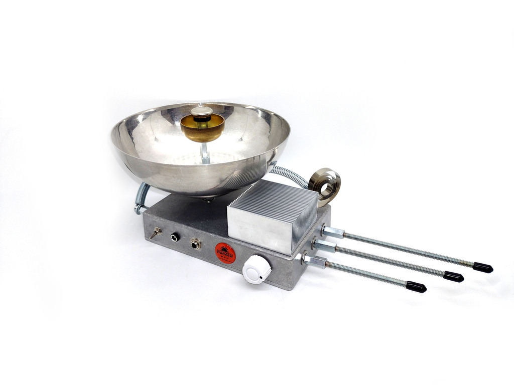
This is the super fun and creative part, install it into a box. I like to use rugged aluminum enclosures, but cigar boxes, metal gift or candy tins, and even Tupperware will work. Ideally you want something that accepts vibration, will resonate, and is sturdy enough for the vibration of the attachments you use.
What attachments are good for Vibratory Sound Boxes?

Some of my favorite items to use for electro-acoustic sound boxes..
- Springs (of course)
- Guitar strings – lots of variation for these
- Bells
- Rubber Bands
- Resonate Bowls
- DIY Kalimbas – can be made with metal or wood
- Heat Sinks
- Threaded Rod
- Heavy Bristled Brushes
- Anything that vibrates
Mods
These are all relatively simple mods aside from Gain Control.
Volume Control
Add a 100k potentiometer between the board output and the output jack, be sure to connect lug 1 to ground
Input Sensitivity Control
Add a 100k potentiometer between to the positive of the piezo and the board
Gain Control
Wire a 10uF capacitor and a 5k potentiometer between pins 1 and 8 of the LM386
Feedback Loop
5-10k potentiometer between input and output jack, I would use a switch to turn it off and on.
This technique works on just about everything that has an input and an output, from keyboards to tape players.
Power Switch
Wire a toggle switch between the positive lead of the battery snap and the positive hole on the PCB.
Momentary Kill/Stutter
Add a Normally Open push button to the output jacks positive and ground tabs, when you push button you momentarily “mute” the sound by forcing the signal to ground.
Thanks again for supporting POTAR Design Devices!
